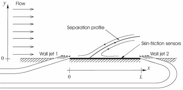
– Alam, M.-R., Liu, W and Haller, G. “Closed Loop Separation Control: An Analytic Approach”, Physics of Fluids, 18 (4): Art. No. 043601 APR 2006. (PDF)

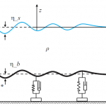
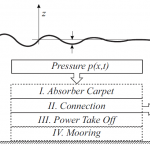
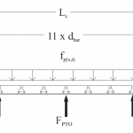
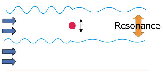
The energy stored in the carpet per unit area for a undamped system is described as


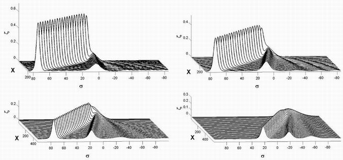


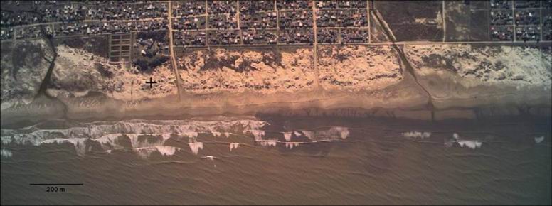
ContinentalShelfResearch29(2009)503–514)


